Geometric Area Lights
Geometric Area Lights
March 2013
Introduction
RPS 18 introduces new support for Geometric Area Lights, as envisioned in the original RenderMan Specification, but in a modernized context. PRMan's implementation provides the expressivity of the initial design, but is also engineered to free the renderer from the requirement that shaders be evaluated every time lighting contributions need to be computed, allowing for improved efficiency. Additionally, the implementation reduces the workload of balancing sample counts over many lights - the distribution of samples between lights is automatically determined from a single budget.
PRMan's Geometric Area Lights were designed with very specific goals:
- Never execute light shaders when determining lighting of a shading point
- Support full importance sampling, with arbitary sample counts (not limited to a minimum of one sample per light)
- Light sampling should be proportional to potential contribution
- Support arbitrary geometry for emission
- Emission profile supports texturing of emissivity and control of directions/emission profile, IES.
- Lights don't dictate sample counts, sample counts may be multiplied for the purposes of increasing a specific light's shadowing.
Using Geometric Area Lights is straightforward and builds upon the lighting integrator directlighting. Emissivity of a surface is programmable via a new shader call - emit(). Two new geometry types have been introduced to support distant and environment lights. Finally, a meaningful implementation has been given to the AreaLightSource call in the Renderman Interface Specification.
The Interface
Area Light shaders can be created with the appropriate calls in prelighting().
To emit light from an area light source:
class geolight (float intensity = 1;
                color lightColor = 1)
{
    public void prelighting(output color Ci, Oi)
    {
        color emission = intensity * lightColor;
        emit(emission);
    }
}

# In RIB

AreaLightSource "geolight" "myLightHandle" ....
Patch ....
A light may also define the color emitted by the geometry of an area light source visible to the camera in the surface() method, just like any other type of geometry:
class geolight (float intensity = 1;
                color lightColor = 1)
{
    public void prelighting (output color Ci, Oi)
    {
        color emission = intensity * lightColor;
        emit(emission);
    }

    public void surface(output color Ci, Oi) {
        Ci = intensity * lightColor;
    }
}
In RIB:
AreaLightSource "geolight" "myLightHandle" ....
Surface "geolight" ....
Patch ....
The emit() call
The arguments to emit() describe the emissivity of the surface to the renderer. It runs in a context much like that of a surface shader. That is, P represents points on the emitting surface (not a surface being illuminated). The shadeop must be present in the prelighting() method of an area light source shader. The points, P, are generated from the geometry to which the area light source is attached.
emit(uniform color, ...)   // constant luminaire
emit(varying color, ...)   // textured luminaire (constant values are detected automatically)
In addition, the following optional parameters are supported:
| Name | Type | Description |
|---|---|---|
| "direction" | varying vector | defaults to N, emission direction |
| "cosinepower" | uniform float >=1.0 | specifies a power for cosine power. Larger values make the light emit more strongly in the direction specified - giving a focusing effect. A Value of 1 is default and specifies that the light contribution is simply due to the form factor of a portion of the light, and is not further focused. |
| "spotcosinepower" | uniform float >0 | applies a cosine power like falloff to a light against the spot orientation space (shader space). It defaults to 0 and can be any number > 0; -ve disables. This is unlike "cosinepower", which can be thought of more like a 'grid' or 'snoot' on a light - it makes the rays more single-direction. Instead, "spotcosinepower" shapes the overall profile, and may be combined with "coneangle" and "penumbraangle". |
| "environmentmap" | string | specify map name for env light (environment lights only) |
| "filteredimportance" | uniform float 0|1 | perform filtered importance sampling or not (currently implemented for environment lights only) |
| "areanormalized" | uniform float 0|1 | Specifies that the emissivity should be divided by the area of the light. Thus rescaling the light does not make the lighting in the scene brighter. Note that for large light sources, the incoming light's interaction with the brdf is still in play (e.g. N.L for diffuse surfaces), so lighting will not be constant with differing light scales in these cases. |
| "portal" or "portals" | uniform string, uniform matrix, uniform string[] or uniform matrix[] | Specifies a set of portals through which light may flow - either predefined coordinate system names are supplied, or matrices representing the space of each portal. The space is defined -1 to 1 in xy. |
| "blocker" or "blockers" | uniform string, uniform matrix, uniform string[] or uniform matrix[] | Specifies a set of blocker coordinate systems in which light contribution is modified. Either predefined coordinate system names are supplied, or matrices representing the space of each blocker. The space is defined -1 to 1 in xyz. |
| "blockershape" or "blockershapes" | uniform vector, or uniform vector[] | Specifies the shape of the blocker (e1,e2,falloffDistance). See the blocker documentation for more information. |
| "blockermultiplier" or "blockermultipliers" | uniform float, or uniform float[] | Multiplies the light contribution by the specified amount. This is multiplicative with the diffusecontribution and specularcontribution. |
| "blockerdiffusemultiplier" or "blockerdiffusemultipliers" | uniform float, or uniform float[] | Multiplies the light diffuse contribution by the specified amount. This is multiplicative with the diffusecontribution. |
| "blockerspecularmultiplier" or "blockerspecularmultipliers" | uniform float, or uniform float[] | Multiplies the light specular contribution by the specified amount. This is multiplicative with the specularcontribution. |
| "gobo" or "gobos" | uniform string, uniform matrix, uniform string[] or uniform matrix[] | Specifies a set of gobo coordinate systems for gobos. Either predefined coordinate system names are supplied, or matrices representing the space of each gobo map. The space is defined -1 to 1 in xy. |
| "gobomap" or "gobomaps" | uniform string, uniform string[] | Specifies the map name for each gobo. |
| "diffusecontribution" | uniform float | Specifies the light's contribution to the diffuse lobe. |
| "specularcontribution" | uniform float | Specifies the light's contribution to the specular lobes. |
| "iesprofile" | uniform string | Specifies an IES profile to be read (if not ""). The profile can also be specified via a map (see below). Note: this parameter cannot be used with environment or distant lights. |
| "profilemap" | uniform string | Specifies a latlong profile to be read (if not ""). Note: this parameter cannot be used with environment or distant lights. |
| "profilerange" | uniform float | Specifies the number of degrees the profile represents. Smaller numbers allow maps representing say 90 degrees to be used, (the default is 180 degrees). Any value > 0 is permissible; -ve values disable remapping. |
| "profilespace" | uniform string | Specifies the space which the profile map or conenangle is specified. The default is "object" space. |
| "coneangle" | uniform float | Restricts light to the specified number of degrees. In combination with the iesprofile or profilemap options, maps the specified cone to the profile. |
| "penumbraangle" | uniform float | Specifies the penumbra angle for spotlights (does not apply if an iesprofile or profilemap has been specified). |
| "penumbraexponent" | uniform float | Specifies the exponent for penumbra falloff for spotlights (does not apply if an iesprofile or profilemap has been specified). |
| "fixedsamplecount" | uniform float |
|
| shadowing parameters | (see below) | (see below) |
By default, the emission is a single-sided cosine lobe about N. Tighter lobes may be constructed with cosine power other than 1, which adjusts the distribution to be more concentrated about the emission direction. The emission profile is stored away and used by the system to build its lighting database.
Environment Lighting
Environment lights operate on a very large sphere that encompasses the bounds of the scene on camera. The geometry representing this special type of area light source is specified as follows:
AreaLightSource "envlightshader" "myEnvLightSource"
Geometry "envsphere"
Environment lights are purely directional - that is to say they ignore any translation applied to them. They may be oriented by placing transforms before the geometry call.
The shader's emit() shadeop is expected to classify the area manifold/shape via the following interface:
emit(scale,.... "environmentmap" "mapname.tx".... )
environmentmap is used in combination with the color passed to emit to specify intensity. If the mapname is empty, then the actual code in the prelighting method is run and the compute color passed to emit() is used to light the environment sphere geometry instead.
Alternatively, if the environmentmap parameter is "", a manifold is automatically constructed, and the light's emit() method run on it. The color passed to emit() is captured and lighting will be performed from it. This permits generative environment maps.
Distant Lights
Distance lights operate similar to environment lights, however the geometry is specified as follows:
AreaLightSource "distantlightshader" "myLightSource"
Geometry "distantlight" "constant float anglesubtended" 5
The shader's emit() shadeop is again used to provide the light emitted from the distant lightsource. Distant lights emit light along the -ve Z direction.
Shadowing
Shadowing terms/methods may be specified by additional args to emit().
| Name | Type | Description |
|---|---|---|
| "adaptiveshadow" | uniform float 0|1 | enable adaptive shadowing |
| "shadowmap" or "shadowmaps" | string or string[] | Specify areashadow maps to be traced against for shadowing purposes |
| "shadowbias" | uniform float | Specify bias for ray-traced shadowing purposes |
| "shadowmapbias" | uniform float | Specify bias for area shadow map shadowing purposes |
| "shadowmapbias2" | uniform float | Specify bias for area shadow map shadowing purposes (see areashadow) |
| "shadowmaxdist" | uniform float | Maximum hit distance for ray tracing shadows |
| "subset" | string | Specify tracegroup subsets for ray-traced shadowing purposes |
| "excludesubset" | string | Specify tracegroup subsets to be excluded from shadowing |
| "raytraceshadow" or "raytraceshadows" | uniform float 0|1 | Perform ray-traced shadowing or not |
| "samplebase" | uniform float | Specify samplebase to be applied when shadowing (see areashadow) |
| "shadowhitmode" | string | Specify whether to evaluate shaders for opacity when shadowing using ray tracing - "default", "primitive", "shader" or "cache". (See areashadow().) |
| "shadowhitsides" | string | Specifies which side(s) of one-sided surfaces can be hit by the rays. The possible values are "front", "back", and "both". The default is "both". |
| "shadowweightthreshold" | uniform float | Specify threshold below which to cull shadow rays (see areashadow()). |
| "usemotionbias" | uniform string | controls application of ray origin compensation for motion when Attribute "trace" "int samplemotion" is set. This compensation offsets the ray origins by t * dPdtime for each ray. Valid settings are "auto", "on", and "off". The default is "auto", which preserves the behavior of version 16.0. This compensates only when the origin == P. Setting "on" always applies compensation, "off" never applies it. |
| "useshadowmethod" | uniform float 0|1 | Invoke the light's shadowSamples() method rather than performing built-in shadowing. |
| "shadowtint" | uniform color | Specify tint of completely shadowed areas |
The default shadowing mechanisms can be specified in RIB and would be applicable to all lights unless they chose to override it when emit() runs, i.e. at emission capture time.
The Interface to directlighting()
directlighting() takes a list of named shader handles. This continues to be the case, but lights that are geometric area lights are not executed; instead, they are evaluated from the database.
Lights are evaluated and hit tested in just the expected way - they use samples generated by the light and hit brdf samples against the light where there are evaluated. The key difference is that the sample counts are proportional to the contribution. Lights that cannot contribute energy do not have any samples and those with minimal contribution get a small number of samples, whereas those that may contribute a lot get more samples.
The "arealightsamples" parameter controls the number of samples to use for area lights. If not set, then Option "shading" "int directlightingsamples" is used. If "arealightsamples" is not provided, or if the value is -1, then automatic determination of the sample count is performed, using importance as a culling metric on the option value.
Obtaining Diffuse, Specular, and Other Outputs
directlighting() provides the following outputs:
| Name | Type | Description |
|---|---|---|
| "diffuseresult" | output varying color | Returns the diffuse only portion of the direct lighting |
| "specularresult" | output varying color | Returns the specular only portion of the direct lighting |
| "unshadowedresult" | output varying color | Returns the unshadowed result of the direct lighting |
| "unshadoweddiffuseresult" | output varying color | Returns the unshadowed diffuse only portion of the direct lighting |
| "unshadowedspecularresult" | output varying color | Returns the unshadwowed specular only portion of the direct lighting |
In addition, directlighting() can group results for manipulation during compositing. To do this, lights that you need separate outputs from must have a string parameter named "__group". For example:
class geolight (float intensity = 1;
                color lightColor = 1;
                string __group = "groupname";
                )
{
    public void prelighting(output color Ci, Oi)
    {
        color emission = intensity * lightColor;
        emit(emission);
    }
}
The value of the group may also be specified in RIB, as for any other shader parameter.
To obtain grouped outputs, a list of groups must be passed to directlighting() via the "lightgroups" parameter. This is an array of groups. All other grouped outputs return their results in color arrays that are ordered as specified by the "lightgroups" parameter.
| Name | Type | Description |
|---|---|---|
| "lightgroups" | string [] | Specifies which light groups are to be returned for the following optional outputs. |
| "groupedresults" | output varying color[] | Returns the grouped results of direct lighting per group specified in the "lightgroups" parameter. |
| "groupeddiffuseresults" | output varying color[] | Returns the grouped diffuse portion of the direct lighting per group specified in the "lightgroups" parameter. |
| "groupedspecularresults" | output varying color[] | Returns the grouped specular portion of the direct lighting per group specified in the "lightgroups" parameter. |
| "groupedunshadowedresults" | output varying color[] | Returns the grouped results of unshadowed direct lighting per group specified in the "lightgroups" parameter. |
| "groupedunshadoweddiffuseresults" | output varying color[] | Returns the grouped diffuse portion of the unshadowed direct lighting per group specified in the "lightgroups" parameter. |
| "groupedunshadowedspecularresults" | output varying color[] | Returns the grouped specular portion of the unshadowed direct lighting per group specified in the "lightgroups" parameter. |
Diffuse MIS
By default, Multiple importance sampling is not done on the diffuse lobe. However, that option is available and will produced improved quality when geometric area lights are close to a surface being illuminated.
To use diffuse MIS, you must do two things: firstly, your surface shader needs to generate samples for the diffuse lobe. It must generate samples slightly differently than the specular ones.
public void genDiffuseSamps(stdrsl_ShadingContext ctx;
                            uniform float nsamples;
                            output __radiancesample samples[])
{
    // Generate local orthogonal coordinate system
    normal Nn = normalize(N);
    vector Tn = normalize(dPdu ^ Nn); // tangent
    vector Bn = Tn ^ Nn; // bitangent

    // Resize the samples array
    uniform float len = arraylength(samples);
    resize(samples, len+nsamples);

    uniform float i;
    for(i=0;i<nsamples;i+=1) {
        // Generate a random direction on the the hemisphere defined by the
        // normal.  Cosine distribution: higher probability near the north
        // pole than near the equator.
        float cosTheta = random();
        float sinTheta = sqrt(1 - cosTheta * cosTheta);
        float phi = random() * M_TWOPI;
        vector Ln = (Nn * cosTheta +
                     Tn * sinTheta * cos(phi) +
                     Bn * sinTheta * sin(phi));
        samples[len+i]->direction = Ln;
        // These samples should go out a long long way (infinity)
        samples[len+i]->distance = 1e20;
        // Compute the brdf for the generated direction

        float ndotl = Ln.Nn;
        ndotl = max(0,ndotl);
        samples[len+i]->accumulatedMaterialResponse = m_diffColor*ndotl*M_INVPI;
        samples[len+i]->materialResponse = 0;
        // Set the materialPdf for this sample
        samples[len+i]->materialPdf = M_INVPI;
    }
}
Note that for diffuse samples, the material response must be placed in accumulatedMaterialResponse _not_ the materialResponse field. Care should be taken to zero the materialResponse field for diffuse samples, and vice versa for specular samples.
Secondly, the surface shader should add "diffusemis",1 to the arguments of directlighting().
Portals
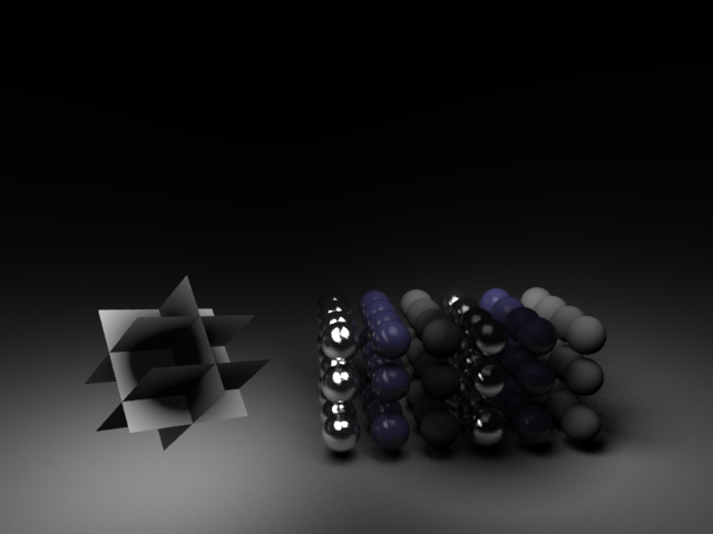
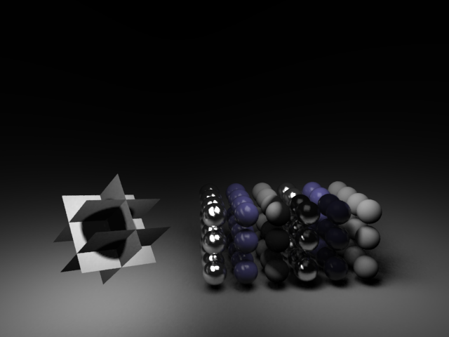
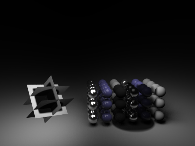
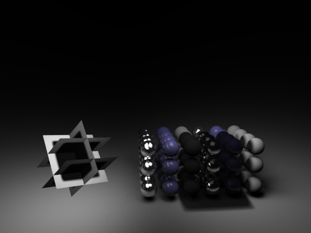
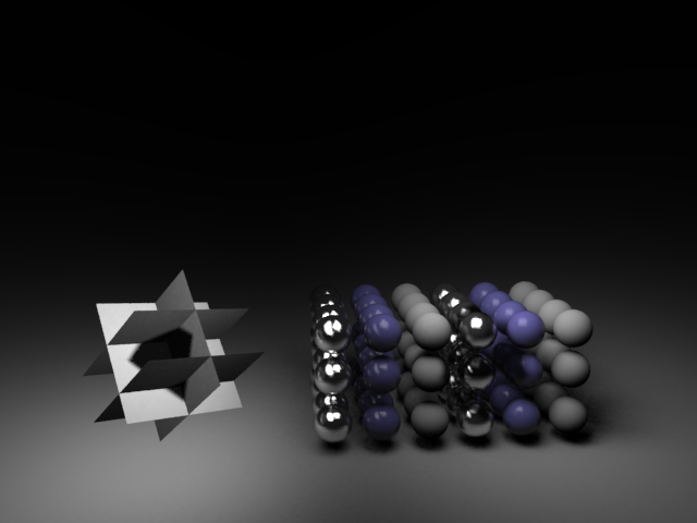
Portals specify planes through which light must flow if it is to contribute to a surface's lighting. More importantly, portals are used to provide visibility hints to the renderer. Consider the following scene with geoemtry in a box, where a small aperture is the only way for light to get into the box.
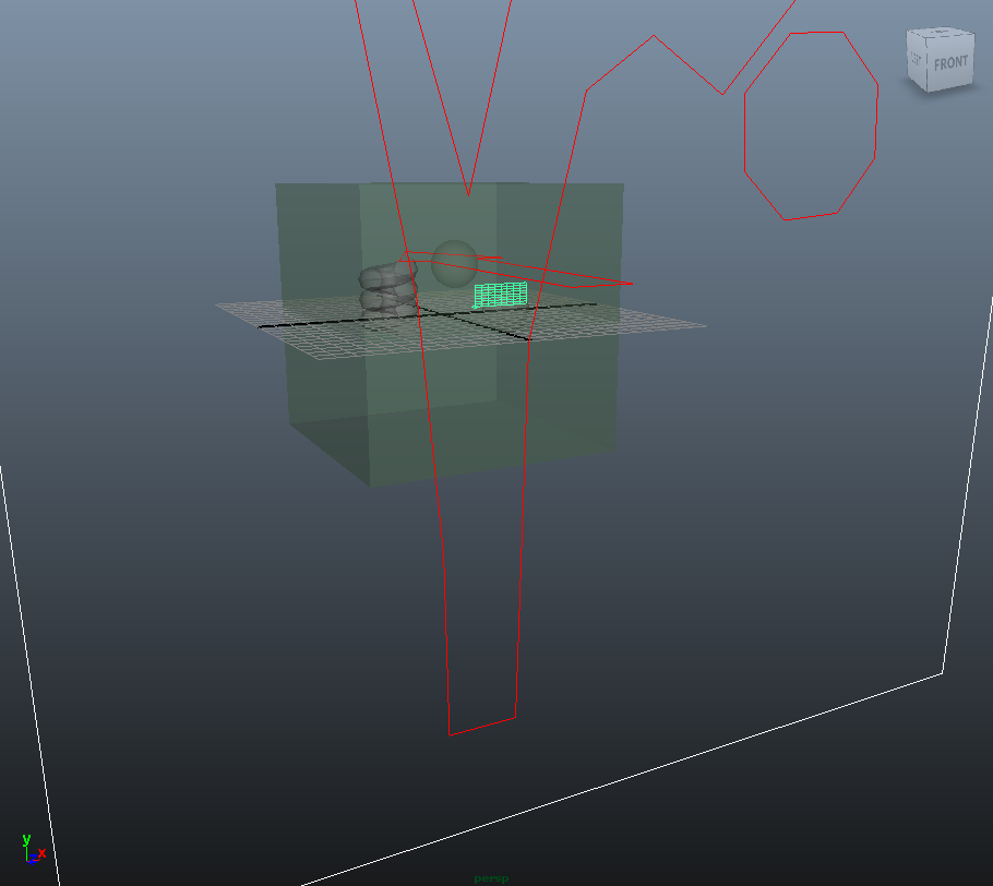
When the area light is large, or contains bright areas that are shadowed by the geometry in the scene, noise is increased as many of the lights samples are "wasted" because they are shadowed by geometry. It would be considerably better to select samples from the light that are actually visible. Portals, when placed over the aperture, will cause the renderer to predominantly select light samples that are visible and will prevent it from selecting completely invisible areas of the light.
Using 256 samples for a light still results in noise because the majority of the arealight is shadowed with respect to the interior of the box.
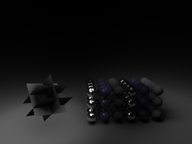
By adding a portal that covers the aperture, noise is significantly reduced.
Note that the illumination of the exterior of the box is not present in the latter image because the light does not pass through the portal.
Blockers
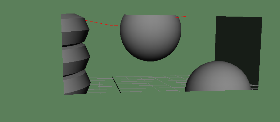
Blockers allow for regional modification of the diffuse and specular contributions from a light. For example, they provide a way to control highlights in a region, separately from the general specular or diffuse contribution for a light.
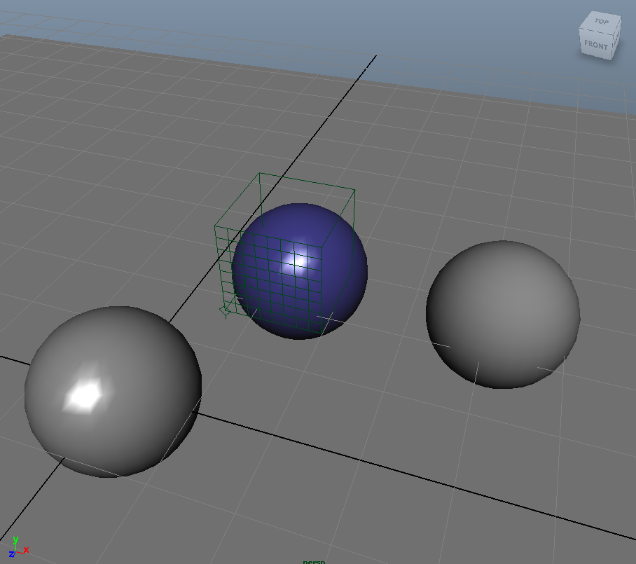
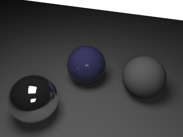
Consider the following scene with two area lights:

By putting a blocker over one of the highlights on the blue sphere and attaching it to the relevant light, we can control that light's specular contribution separately from its diffuse - without impacting the specular contribution of any other light.
To do this, a coordinate system "blocker" is defined in RIB, and the following parameters are added to emit():
string blockerspace = "blocker";
uniform float blockerspecularcale = 0.05;
emit(....
        "blockers",blockerSpace,
        "blockerspecularmultiplier", blockerspecularscale
    );
The blocker can also be used to control diffuse contribution:
This time we control the diffuse multiplier:
string blockerspace = "blocker";
uniform float blockerdiffusescale = 0.05;
emit(....
        "blockers",blockerSpace,
        "blockerdiffusemultiplier", blockerdiffusescale
    );
A blocker is defined as a superellipsoid. It takes three arguments to control its shape. The superellipsoid is parameterized implicitly as:
F(x,y,z) = ( (x*x ^ (1.0f/e2)) + (y*y ^ (1.0f/e2)) ) ^ (e2/e1) + z*z ^ (1.0f/e1);
A vector parameter to emit blockershape specifies (e1,e2,falloff), where falloff describes the distance from the surface of the superellipsoid at which there is no influence from the blocker. Here we show examples where both the diffuse and specular contributions have been scaled near to 0.
The default setting of (e1=1,e2=1,falloff=1) gives a spherical region:
Increasing the falloff (e1=1,e2=1,falloff=4) gives a larger region of influence outside the shape. Inside the shape the influence is always 1.
Decreasing the falloff (e1=1,e2=1,falloff=.1) gives a smaller region of influence outside the shape - and hence a sharper transition.
Cylindrical regions result from (e1=0.1,e2=1,falloff=.1):
Cuboid regions result from (e1=0.1,e2=0.1,falloff=.1):
Other interesting shapes are also possible (e1=2,e2=2,falloff=.1):
And (e1=1,e2=0.1,falloff=.1):
Gobos
Like blockers, gobos are defined within some coordinate space. A gobo is a map-based filter through which light passes. It is defined -1 to 1 in the xy space you pass.
To define a gobo, pass a coordinate system "gobo" to emit(). Such a coordinate system is defined in RIB, or it may be a matrix.
string gobospace = "gobo";
string gobomap = "treeline.tx";
emit(....
        "gobos",gobospace,
        "gobomaps", gobomap
    );
Like blockers, any number of gobos may be applied.
Notes
Users should note the following conditions:
Hierarchical Acceleration
Hierarchical acceleration is fully supported for accelerating sampling of the light database. An option controls the quality of the hierarchy construction:
Option "shading" "float directlightinghierarchyerror" 0.005To disable hierarchical acceleration, simply set the value to zero:
Option "shading" "float directlightinghierarchyerror" 0
- Procedurals
- These should use the RI_IMMEDIATESUBDIVIDE crack parameter to the Procedural2() interface to ensure lights inside procedurals are correctly added to the light database.
- Shadowing
- RIB-level defaults for shadowing are not currently available and the shadow quality control is not implemented.
- Visibility
Perhaps not immediately obvious is the fact that you should be careful with visibility attributes on geometric area lights. Usually you do not want lights to be specular-visible or diffuse-visible because that transport is handled by directlighting(). Therefore,
Attribute "visibility" "int specular" [0]
                       "int diffuse" [0]
                       "int transmission" [0]
probably represents reasonable settings for most lights, with transmission visibility usual only for some primary visible lights that also have surface shaders.
- ShadingRate
ShadingRate is respected for geometric area lights. For constant luminaires, improved performance will result from setting a numerically high value, e.g.:
ShadingRate 1000
For luminaires with textures or higher cosine powers, or for lights used with portals, a standard ShadingRate should be used.
Care should be exercised when specifying shading rates for lights with areas that are extremely large relative to the viewport. Consider a camera with a very small field-of-view in combination with a large rectlight that projects on to the viewport such that its total projected area is 1,000x1,000 times larger than the fraction visible to the frustum. (Geometric area lights always use spherical projection.) In this case a shading rate of 100 and a rendering resolution of 1,000x1,000 would result in a micropolygon size of 10 pixels on a side, which would in turn result in the light being split and diced into on the order of 10,000x10,000 micropolygons. This is likely too high a dicing rate and the shading rate should be increased to compensate.
Appendix A: An Example
The RIB file:
#======================================================
# A trivial test harness for area light sources
# NOTE: This example uses the "plausibleArealight" shader
#   which has been modified to use the emit() call
#======================================================
Quantize "rgb" 0 0 0 0
Display "dielectric" "framebuffer" "rgba" "int merge" [0]
Format 640 480 1
PixelSamples 3 3
Projection "perspective" "fov" 45
Translate 0 0 10
ShadingRate 1

Option "shading" "int directlightingsamples" 64

WorldBegin
Attribute "visibility" "int specular" [1]
                       "int diffuse" [1]
                       "int transmission" [1]
Attribute "trace" "int maxdiffusedepth" [1] "int maxspeculardepth" [1]

IfBegin "1"
      #---------------------------
      # This is the new area light source technique,
      # note the Polygon on which it emits light
      #---------------------------
      AttributeBegin
      Attribute "visibility" "int specular" [0]
                             "int diffuse" [0]
                             "int transmission" [0]
      Scale 10 4 1 # nonsquare rect
      Translate 0 10 -10  # above right the camera

      AreaLightSource "plausibleArealight" "mylighthandle" "intensity" 150
                      "color lightcolor" [1 1 1] "float maxSamples" 64
      Polygon "P" [-0.5 -0.5 0   0.5 -0.5 0    0.5 0.5 0   -0.5 0.5 0]

      AttributeEnd
Else
      #---------------------------
      # This is the old psuedo-area light source technique
      #---------------------------
      AttributeBegin
      Attribute "visibility" "int specular" [0]
                                                 "int diffuse" [0]
                                                 "int transmission" [0]
      Scale 10 4 1 # nonsquare rect
      Translate 0 10 -10  # above right the camera

      LightSource "plausibleArealight" "mylighthandle" "intensity" 150
                                      "color lightcolor" [1 1 1] "float maxSamples" 64
      AttributeEnd
      Illuminate "mylighthandle" 1
IfEnd

AttributeBegin
Translate -1.5 -2 0
Surface "plausibleDielectric" "float roughness" .08
                       "color surfaceColor" [1 0 0]
                       "float indirectDiffuseMaxVar" [0]
Sphere 1 -1 1 360

AttributeEnd
AttributeBegin
Surface "plausibleDielectric" "float roughness" .03
                       "color surfaceColor" [0 1 0]
                       "float indirectDiffuseMaxVar" [0]
Sphere 1 -1 1 360
AttributeEnd


AttributeBegin
Translate 1.5 2 0
Surface "plausibleDielectric" "float roughness" .01
                       "color surfaceColor" [0 0 1]
                       "float indirectDiffuseMaxVar" [0]
Sphere 1 -1 1 360
AttributeEnd

Scale 10 10 .1
Translate 0 0 -1
Surface "plausibleMatte"
Geometry "cube"

WorldEnd