Photon Mapping for General Shaders
Photon Mapping for General Shaders
June 2007 (Revised June 2010)
1 Introduction
Photon mapping has been a part of PRMan since version 11.0. However, the light sources had to have hard-coded distance fall-offs and the surface materials were restricted to a fixed, limited set of materials (matte, translucent, chrome, transparent, glass, and water). Perhaps the biggest limitation was that textures could not be used in the photon tracing phase.
PRMan 13.5 introduced a much more general and flexible approach to photon mapping. The approach works with very general shaders, including area light sources, surface textures and displacement shaders. The main drawback is that it requires the direct illumination and the surface colors to be baked into point cloud files. The purpose of this application note is to provide examples for the use of photon maps for caustics and global illumination with very general light source and surface shaders.
2 Sampling Illumination and Scattering Coefficients
In order to control the emission and and tracing of photons, we first need to bake the the illumination and surface colors.
2.1 Baking Direct Illumination
Photon emission corresponding to simple light sources (point lights, spot lights, and directional lights - even with "barn doors", cucoloris, and projected textures) is fairly straightforward. However, general light source shaders can also have unnatural distance fall-off, fake shadow positions, fake position of the highlights, etc. It is difficult to make the photon emission match such shaders. However, here we will use a different approach: evaluate the light source shaders at the surface points by rendering the direct illumination from the light sources. This basically treats each light source shader as a "black box" that is fully characterized by its illumination on the surfaces in the scene.
In order to specify the direct illumination, we need to render the scene with a light source shader that bakes _irradiance, L, and _area using the bake3d() function. (L is not necessary if all surfaces are diffuse - more on this below.)
As an example, we'll use a box with two teapots and texture and displacement maps. The scene is illuminated by three light sources. They store illumination for use in photon emission - three light sources bake into the same point cloud file. Below are the two light source shaders used. The shader 'myspotlight' is a spot light with no distance fall-off by default; 'projectorlightxz' projects a light texture (in the x-z plane) similar to a slide projector. The shadows are computed with ray tracing.
The line "L = L;" is a necessary trick to avoid an unwanted optimization, thus ensuring that the light source shader is being run on all shading grids.
light
myspotlight(
  float intensity = 1;
  color lightcolor = 1;
  float falloff = 0;   // default: no fall-off
  point from = point "shader" (0,0,0);   // light position
  vector dir = (0, -1, 0);   // light direction (center of cone)
  float coneangle = radians(30);
  float conedeltaangle = radians(5);
  string filename = "";)   // point cloud file
{
  uniform float cosoutside = cos(coneangle);
  uniform float cosinside = cos(coneangle-conedeltaangle);
  vector dirn, Ln;
  float dist, cosangle, atten;
  float a = area(Ps, "dicing"); // micropolygon area

  dirn = normalize(dir);

  illuminate(from, dirn, coneangle) {
    L = L; // trick to avoid skipping light source shader call !!
    dist = length(L);
    Ln = L / dist;
    cosangle = dirn.Ln;
    atten = pow(dist, -falloff);   // distance fall-off
    atten *= smoothstep(cosoutside, cosinside, cosangle); // cone edge
    Cl = atten * intensity * lightcolor;
    Cl *= transmission(Ps, from);   // ray traced shadow

    // Compute irradiance to bake
    float dot = -(Ln.N) / length(N);
    color irrad = Cl * abs(dot);

    // Bake the direct illum, illum direction, and micropolygon area
    if (filename != "" && (irrad[0] > 0 || irrad[1] > 0 || irrad[2] > 0))
        bake3d(filename, "_irradiance,L,_area", Ps, N, "interpolate", 1,
               "_irradiance", irrad, "L", Ln, "_area", a);
  }
}
light
projectorlightxz(
  float intensity = 1;
  color lightcolor = 1;
  float minx = -1, maxx = 1, minz = -1, maxz = 1;
  string texturename = "";
  point from = point "shader" (0,0,0);   // light position
  vector dir = (0, -1, 0);   // light direction (don't illum behind)
  string filename = "";)   // point cloud file name
{
  uniform float dx = maxx - minx, dz = maxz - minz;
  vector Ln;
  float x = Ps[0], z = Ps[2], s, t;
  float a = area(Ps, "dicing"); // micropolygon area

  illuminate(from, dir, PI/2) {
    if (minx <= x && x <= maxx && minz <= z && z <= maxz) {

      // Compute illumination (ignoring shadow)
      Cl = intensity * lightcolor;
      if (texturename != "") {
        s = (x - minx) / dx;
        t = (z - minz) / dz;
        Cl *= texture(texturename, s, t);
      }

      // Compute ray-traced shadow
      Cl *= transmission(Ps, from);

      // Compute irradiance to bake
      Ln = normalize(L);
      float dot = -(Ln.N) / length(N);
      color irrad = Cl * abs(dot);

      // Bake the direct illum, illum direction, and micropolygon area
      if (filename != "" && (irrad[0] > 0 || irrad[1] > 0 || irrad[2] > 0))
        bake3d(filename, "_irradiance,L,_area", Ps, N, "interpolate", 1,
               "_irradiance", irrad, "L", Ln, "_area", a);
    }
  }
}
For completeness, the three displacement shaders are listed in Appendix A. The use of displacement shaders here demonstrates that displacement works fine with photon mapping.
Here is the RIB file for the scene:
FrameBegin 1

  Format 400 400 1
  ShadingInterpolation "smooth"
  PixelSamples 4 4
  Display "box_bake_direct" "it" "rgba"
  Projection "perspective" "fov" 30
  Translate 0 0 5

  DisplayChannel "color _irradiance"
  DisplayChannel "vector L"
  DisplayChannel "float _area"

  WorldBegin

    Attribute "cull" "hidden" 0   # ensure illum is baked behind objects
    Attribute "cull" "backfacing" 0   # ensure illum is baked on backsides
    Attribute "dice" "rasterorient" 0   # view-independent dicing

    # Turn on ray-traced shadows
    Attribute "visibility" "transmission" 1
    Attribute "trace" "bias" 0.0001

    # Turn on displacements
    Attribute "trace" "displacements" 1
    Attribute "displacementbound" "sphere" 0.1 "coordinatesystem" "world"

    # Light sources (each bakes its own illumination)
    LightSource "myspotlight" 1   # wide white spot
       "point from" [0.5 0.999 0] "vector dir" [0 -1 0] "float coneangle" 1.2
       "string filename" "box_direct.ptc"
    LightSource "myspotlight" 2   # narrow red spot
       "point from" [0.5 0.999 -0.5] "vector dir" [-0.3 -1 0.3]
       "float intensity" 0.5 "color lightcolor" [1 0 0] "float coneangle" 0.3
       "string filename" "box_direct.ptc"
    LightSource "projectorlightxz" 3   # project bright prman logo texture
       "point from" [-0.7 0 0.75] "vector dir" [0 1 0]
       "float minx" -0.9 "float maxx" -0.4
       "float minz" 5.5 "float maxz" 5.99
       "float intensity" 2
       "texturename" "prman_logo.tex"
       "filename" "box_direct.ptc"

    Surface "matte"

    # Left wall
    AttributeBegin
      Displacement "dispsinz" "float freq" 22 "float scale" 0.1
      Polygon "P" [ -1 1 -1  -1 1 1  -1 -1 1  -1 -1 -1 ]
        "s" [0 1 1 0] "t" [0 0 1 1]
    AttributeEnd

    AttributeBegin
      Polygon "P" [ 1 -1 -1  1 -1 1  1 1 1  1 1 -1 ]   # right wall
      Polygon "P" [ -1 -1 1  1 -1 1  1 -1 -1  -1 -1 -1 ]   # floor
      Polygon "P" [ -1 1 -1  1 1 -1  1 1 1  -1 1 1 ]   # ceiling
    AttributeEnd

    # Back wall
    AttributeBegin
      Attribute "displacementbound" "sphere" 0.01 "coordinatesystem" "world"
      Displacement "dispmap" "string texturename" "prman_logo.tex"
        "float scale" -0.01
      Polygon "P" [ -1 1 1  1 1 1  1 -1 1  -1 -1 1 ]
        "s" [-1 2 2 -1] "t" [-1 -1 2 2]
    AttributeEnd

    # Left teapot (chrome, but matte in this pass)
    AttributeBegin
      Translate -0.35 -0.999 0.35
      Scale 0.18 0.18 0.18
      Rotate -30 0 1 0
      Rotate -90 1 0 0
      Geometry "teapot"
    AttributeEnd

    # Right teapot (displaced matte)
    AttributeBegin
      ShadingRate 0.25   # dense tessellation for fine displacement details
      Displacement "disppumpkin" "float freq" 9 "float scale" 0.05
      Translate 0.35 -0.999 -0.35
      Scale 0.18 0.18 0.18
      Rotate 30 0 1 0
      Rotate -90 1 0 0
      Geometry "teapot"
    AttributeEnd

  WorldEnd
FrameEnd
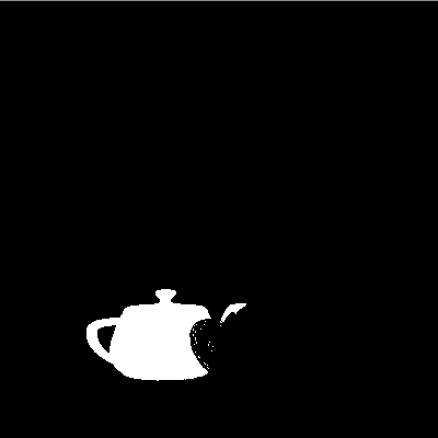
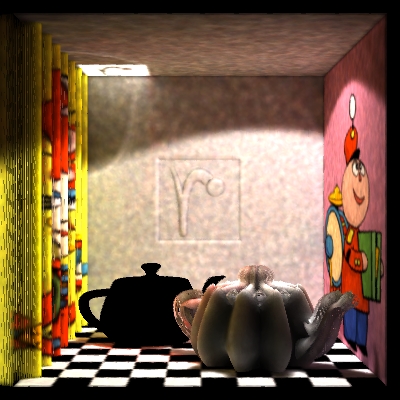
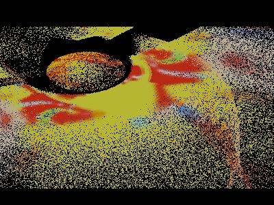
Running this RIB file gives the following illumination image and point cloud "box_direct.ptc":
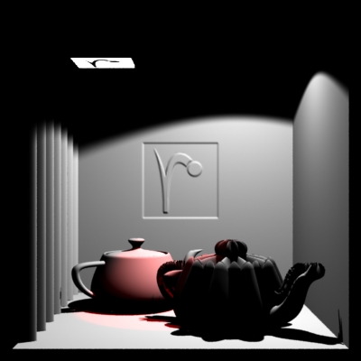
Direct illumination (on matte shader) |
Direct illumination point cloud (channel _irradiance) |
The red illumination is less visible in the image to the right since ptviewer happens to display the gray illumination points on top of the red illumination points. Also note that no points are baked in areas with no illumination.
Special case: If all surfaces are purely diffuse, the L direction does not need to be baked. In that case, it is sufficient to bake the total Cl (the sum of illumination from all light sources) along with the micropolygon area; this can can be done in either the surface shader or in an atmosphere shader.
Potential pit-fall: if multiple light sources write to the same point cloud file (as in the example above) then it is important that the DisplayChannels do not turn on "EliminateDuplicateGrids". If they do, then only points from the first light source will be stored in the point cloud. If EliminateDuplicateGrids has to be on (for netrendering) then baking should be done in a surface shader (or atmosphere shader).
2.2 Baking Scattering Coefficients
To specify the scattering coefficients, the scene must be rendered with surface shaders that bake the scattering coefficients for the surface materials of the objects.
The surface shader 'bake_scattercoeffs' stores scatter coefficients for use in photon tracing: diffuse reflection, specular reflection, diffuse refraction, and specular refraction. (The baking and later lookups rely on the surface normals pointing outward.)
surface
bake_scattercoeffs(string filename = "", displaychannels = "";
                   color specrefl = 0, diffrefr = 0, specrefr = 0;
                   float ior = 1;
                   string texturename = "")
{
  color diffrefl = Cs;
  normal Nn = normalize(N);

  // Multiply diffuse color by texture, if present
  if (texturename != "")
    diffrefl *= texture(texturename);

  // Store scattering coefficients in point cloud file
  bake3d(filename, displaychannels, P, Nn, "interpolate", 1,
         "diffrefl", diffrefl, "specrefl", specrefl,
         "diffrefr", diffrefr, "specrefr", specrefr, "ior", ior);

  Ci = diffrefl * Os;
  Oi = Os;
}
Here is the RIB file:
FrameBegin 1

  Format 400 400 1
  ShadingInterpolation "smooth"
  PixelSamples 4 4
  Display "box_bake_scattercoeffs" "it" "rgba"
  Projection "perspective" "fov" 30
  Translate 0 0 5

  DisplayChannel "color diffrefl"
  DisplayChannel "color specrefl"
  DisplayChannel "color diffrefr"   # unused in this example
  DisplayChannel "color specrefr"   # unused in this example
  DisplayChannel "float ior"        # unused in this example

  WorldBegin

    Attribute "cull" "hidden" 0   # ensure illum is baked behind objects
    Attribute "cull" "backfacing" 0   # ensure illum is baked on backsides
    Attribute "dice" "rasterorient" 0   # view-independent dicing

    # Turn on displacements
    Attribute "trace" "displacements" 1
    Attribute "displacementbound" "sphere" 0.1 "coordinatesystem" "world"

    # Left wall
    AttributeBegin
      Displacement "dispsinz" "float freq" 22 "float scale" 0.1
      Surface "bake_scattercoeffs"
        "string filename" "box_scattercoeffs.ptc"
        "string displaychannels" "diffrefl,specrefl"
        "string texturename" "irma.tex"
      Polygon "P" [ -1 1 -1  -1 1 1  -1 -1 1  -1 -1 -1 ]
        "s" [0 1 1 0] "t" [0 0 1 1]
    AttributeEnd

    # Right wall
    AttributeBegin
      Surface "bake_scattercoeffs"
        "string filename" "box_scattercoeffs.ptc"
        "string displaychannels" "diffrefl,specrefl"
        "string texturename" "tinny.tex"
      Polygon "P" [ 1 -1 -1  1 -1 1  1 1 1  1 1 -1 ]
        "s" [0 1 1 0] "t" [1 1 0 0]
    AttributeEnd

    # Floor
    AttributeBegin
      Surface "bake_scattercoeffs"
        "string filename" "box_scattercoeffs.ptc"
        "string displaychannels" "diffrefl,specrefl"
        "string texturename" "checkerboard10.tex"
      Polygon "P" [ -1 -1 1  1 -1 1  1 -1 -1  -1 -1 -1 ]
        "s" [0 0.995 0.995 0] "t" [0.005 0.005 0.995 0.995]
    AttributeEnd

    # Ceiling
    AttributeBegin
      Color [0.8 0.8 0.8]
      Surface "bake_scattercoeffs"
        "string filename" "box_scattercoeffs.ptc"
        "string displaychannels" "diffrefl,specrefl"
      Polygon "P" [ -1 1 -1  1 1 -1  1 1 1  -1 1 1 ]
    AttributeEnd

    # Back wall
    AttributeBegin
      Color [0.8 0.8 0.8]
      Attribute "displacementbound" "sphere" 0.01 "coordinatesystem" "world"
      Displacement "dispmap" "string texturename" "prman_logo.tex"
        "float scale" -0.01
      Surface "bake_scattercoeffs"
        "string filename" "box_scattercoeffs.ptc"
        "string displaychannels" "diffrefl,specrefl"
      Polygon "P" [ -1 1 1  1 1 1  1 -1 1  -1 -1 1 ]
        "s" [-1 2 2 -1] "t" [-1 -1 2 2]
    AttributeEnd

    # Left teapot (chrome)
    AttributeBegin
      Color [0 0 0]
      Surface "bake_scattercoeffs" "color specrefl" [1 1 1]
        "string filename" "box_scattercoeffs.ptc"
        "string displaychannels" "diffrefl,specrefl"
      Translate -0.35 -0.999 0.35
      Scale 0.18 0.18 0.18
      Rotate -30 0 1 0
      Rotate -90 1 0 0
      Geometry "teapot"
    AttributeEnd

    # Right teapot (matte)
    AttributeBegin
      Color [0.8 0.8 0.8]
      ShadingRate 0.25
      Displacement "disppumpkin" "float freq" 9 "float scale" 0.05
      Surface "bake_scattercoeffs"
        "string filename" "box_scattercoeffs.ptc"
        "string displaychannels" "diffrefl,specrefl"
      Translate 0.35 -0.999 -0.35
      Scale 0.18 0.18 0.18
      Rotate 30 0 1 0
      Rotate -90 1 0 0
      Geometry "teapot"
    AttributeEnd

  WorldEnd
FrameEnd
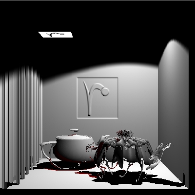
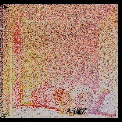
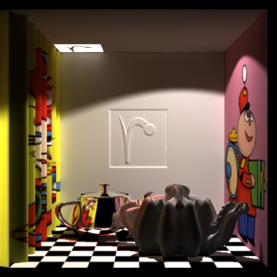
Running this RIB file gives the following image:
Scattering coefficients (diffuse surface color)
And here are the diffuse and specular reflection coefficients of the generated point cloud "box_scattercoeffs.ptc":
Channel 'diffrefl' |
Channel 'specrefl |
In this example, we only baked diffuse and specular reflection coefficients. It is also possible to bake diffuse and specular refraction coefficients as well as the index of refraction (ior).
In this example, all scattering coefficients were baked to a single point cloud file. It is also possible to bake several point clouds, for example one per object in the scene.
3 Photon Emission and Tracing
The next step is photon emission and tracing. The photon emission and tracing is guided by the point clouds baked in section 2.
3.1 Specifying Photon Emission
Photons are emitted in the same way as before: with a photon hider. The new thing is that the photon emission can be specified by a point cloud that is passed with the parameter "emissionpointcloud". For example:
Hider "photon" "emit" 100000 "emissionpointcloud" "box_direct.ptc"
If no emissionpointcloud is specified, PRMan will revert to the old behavior: it will emit photons corresponding (as much as possible) to the light sources in the scene.
3.2 Specifying Surface Materials
The point cloud to use for surface scattering values (diffrefl, diffrefr, specrefl, specrefr, ior) is specified with the Attribute "photon" "shadingmodel" and a filename prepended with "pointcloud:" or "brickmap:". For example:
Attribute "photon" "shadingmodel" "pointcloud:foo.ptc"
Attribute "photon" "shadingmodel" "brickmap:bar.bkm"
The old, predefined surface materials can still be used, too:
Attribute "photon" "shadingmodel" ["matte" | "translucent" | "chrome"
  | "transparent" | "glass" | "water" | "refractive:ior=..." | "dielectric"
  | "absorbing"].
3.3 Example: Photon Emission and Tracing in the Box Scene
In the following RIB file, the illumination point cloud "box_direct.ptc" is used to guide the photon emission and the scattering coefficients in "box_scattercoeffs.ptc" are used for photon tracing.
FrameBegin 1
  Hider "photon" "emit" 1000000 "emissionpointcloud" "box_direct.ptc"

  Format 400 400 1   # not necessary, but makes ptviewer display nicer
  Projection "perspective" "fov" 30   # ditto

  Translate 0 0 5

  WorldBegin

    # The name of the global photon map and caustic photon map files
    Attribute "photon" "globalmap" "box_gpm.ptc"
    Attribute "photon" "causticmap" "box_cpm.ptc"

    # Ray tracing attributes
    Attribute "trace" "maxspeculardepth" 5
    Attribute "trace" "maxdiffusedepth" 5
    Attribute "trace" "bias" 0.0001
    Attribute "trace" "displacements" 1
    Attribute "displacementbound" "sphere" 0.1 "coordinatesystem" "world"

    Attribute "dice" "rasterorient" 0 # view-indep dicing to match ptcloud

    # Use surface scattering values in point cloud box_scattercoeffs.ptc
    Attribute "photon" "shadingmodel" "pointcloud:box_scattercoeffs.ptc"

    # Matte box
    AttributeBegin
      Displacement "dispsinz" "float freq" 22 "float scale" 0.1
      Polygon "P" [ -1 1 -1  -1 1 1  -1 -1 1  -1 -1 -1 ]   # left wall
        "s" [0 1 1 0] "t" [0 0 1 1]
    AttributeEnd
    AttributeBegin
      Polygon "P" [ 1 -1 -1  1 -1 1  1 1 1  1 1 -1 ]   # right wall
      Polygon "P" [ -1 -1 1  1 -1 1  1 -1 -1  -1 -1 -1 ]   # floor
      Polygon "P" [ -1 1 -1  1 1 -1  1 1 1  -1 1 1 ]   # ceiling
    AttributeEnd
    AttributeBegin
      Attribute "displacementbound" "sphere" 0.01 "coordinatesystem" "world"
      Displacement "dispmap" "string texturename" "prman_logo.tex"
        "float scale" -0.01
      Polygon "P" [ -1 1 1  1 1 1  1 -1 1  -1 -1 1 ]   # back wall
        "s" [-1 2 2 -1] "t" [-1 -1 2 2]
    AttributeEnd

    # Left teapot (chrome)
    AttributeBegin
      Translate -0.35 -0.999 0.35
      Scale 0.18 0.18 0.18
      Rotate -30 0 1 0
      Rotate -90 1 0 0
      Geometry "teapot"
    AttributeEnd

    # Right teapot (matte)
    AttributeBegin
      ShadingRate 0.25   # to match pointcloud
      Displacement "disppumpkin" "float freq" 9 "float scale" 0.05
      Translate 0.35 -0.999 -0.35
      Scale 0.18 0.18 0.18
      Rotate 30 0 1 0
      Rotate -90 1 0 0
      Geometry "teapot"
    AttributeEnd

  WorldEnd
FrameEnd
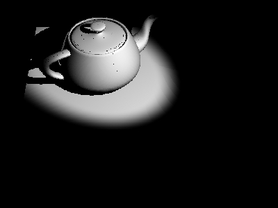
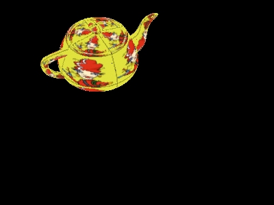
Running this RIB file generates a global photon map, "box_gpm.ptc", with approximately 2.6 million photons. The photon map powers and diffuse surface colors look like this (powers displayed with ptviewer -multiply 50000, since they are very dim):
Photon powers |
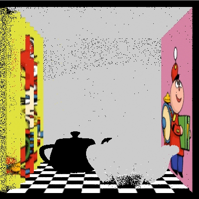
Cs colors at photon positions |
4 Computing the Radiosity Map
Using the photon map's powers and diffuse surface colors, we can compute a radiosity estimate at each photon position. The resulting point cloud is often called a radiosity map. The radiosity map can be computed using the ptfilter stand-alone program. For example:
ptfilter -photonmap -nphotons 200 -threads 4 box_gpm.ptc box_rad.ptc
The image below shows the computed radiosity map (box_rad.ptc) for the box scene example:
Radiosity map (point cloud with 2.6 million points)
5 New Step: Resampling the Radiosity Map
This step ensures that there are no gaps in the radiosity map. This step is only necessary if point-based color bleeding is used for final gathering in the following rendering step, and if the photon map has gaps between photons in areas with little illumination. In our box example, the front of the displacement-mapped diffuse teapot is such an area, as are the floor regions under the teapots.
This is a shader that reads radiosity values from one radiosity map and writes it in another:
surface
resample_radiositymap(string infile = "", outfile = "")
{
  color rad = 0;
  float a = area(P, "dicing"); // micropolygon area

  // Read radiosity values from photon map with precomputed radiosities
  texture3d(infile, P, N, "_radiosity", rad);

  // Store area and radiosity in a new point cloud file
  bake3d(outfile, "_area,_radiosity", P, N, "interpolate", 1,
         "_area", a, "_radiosity", rad);

  // Compute Ci and Oi
  Ci = rad * Os;
  Oi = Os;
}
And here is the RIB file for resampling the radiosity map:
FrameBegin 1

  Format 400 400 1
  ShadingInterpolation "smooth"
  PixelSamples 4 4
  Display "box_resample_radiositymap" "it" "rgba"
  Projection "perspective" "fov" 30
  Translate 0 0 5

  DisplayChannel "float _area"
  DisplayChannel "color _radiosity"

  WorldBegin

    Attribute "cull" "hidden" 0   # ensure illum is baked behind objects
    Attribute "cull" "backfacing" 0   # ensure illum is baked on backsides
    Attribute "dice" "rasterorient" 0   # view-independent dicing

    # Turn on displacements
    Attribute "trace" "displacements" 1
    Attribute "displacementbound" "sphere" 0.1 "coordinatesystem" "world"

    # Same shader for all surfaces
    Surface "resample_radiositymap"
      "string infile" "box_rad.ptc" "string outfile" "box_rad2.ptc"

    # Left wall
    AttributeBegin
      Displacement "dispsinz" "float freq" 22 "float scale" 0.1
      Polygon "P" [ -1 1 -1  -1 1 1  -1 -1 1  -1 -1 -1 ]
        "s" [0 1 1 0] "t" [0 0 1 1]
    AttributeEnd

    # Right wall
    AttributeBegin
      Polygon "P" [ 1 -1 -1  1 -1 1  1 1 1  1 1 -1 ]
        "s" [0 1 1 0] "t" [1 1 0 0]
    AttributeEnd

    # Floor
    AttributeBegin
      Polygon "P" [ -1 -1 1  1 -1 1  1 -1 -1  -1 -1 -1 ]
        "s" [0 0.995 0.995 0] "t" [0.005 0.005 0.995 0.995]
    AttributeEnd

    # Ceiling
    AttributeBegin
      Color [0.8 0.8 0.8]
      Polygon "P" [ -1 1 -1  1 1 -1  1 1 1  -1 1 1 ]
    AttributeEnd

    # Back wall
    AttributeBegin
      Color [0.8 0.8 0.8]
      Attribute "displacementbound" "sphere" 0.01 "coordinatesystem" "world"
      Displacement "dispmap" "string texturename" "prman_logo.tex"
        "float scale" -0.01
      Polygon "P" [ -1 1 1  1 1 1  1 -1 1  -1 -1 1 ]
        "s" [-1 2 2 -1] "t" [-1 -1 2 2]
    AttributeEnd

    # Left teapot (chrome)
    AttributeBegin
      Color [0 0 0]
      Translate -0.35 -0.999 0.35
      Scale 0.18 0.18 0.18
      Rotate -30 0 1 0
      Rotate -90 1 0 0
      Geometry "teapot"
    AttributeEnd

    # Right teapot (matte)
    AttributeBegin
      Color [0.8 0.8 0.8]
      ShadingRate 0.25
      Displacement "disppumpkin" "float freq" 9 "float scale" 0.05
      Translate 0.35 -0.999 -0.35
      Scale 0.18 0.18 0.18
      Rotate 30 0 1 0
      Rotate -90 1 0 0
      Geometry "teapot"
    AttributeEnd

  WorldEnd
FrameEnd
The image below shows the resampled radiosity map (box_rad2.ptc) for the box scene example:
Resampled radiosity map (point cloud with around 693,000 points)
6 Rendering with Final Gathering
All that remains is to render the final image. The radiosity map shown above is obviously too noisy to render directly, so we need to do a final gather to improve the quality. The final gather can be done in two ways:
- Create a brick map from the radiosity map point cloud and use ray-traced final gathering. This approach is described in the Global Illumination application note.
- Point-based color bleeding. This is similar to the color bleeding approach described in Section 3.2 of the Point-based Approximate Ambient Occlusion and Color Bleeding application note. The only difference is that the point cloud in this case represents global illumination, not direct illumination.
In this example we'll use the point-based approach, since it is usually faster. This is a shader that computes point-based color bleeding (final gathering):
surface
matte_ptbased_globillum(uniform string texturename = "";
                        uniform string globillumfile = "", causticfile = "";
                        float Kd = 1;
                        float maxvariation = 0.0;
                        float causticphotons = 100)
{
  color irrad = 0, tex = 1;
  normal Nn = normalize(N);

  // Compute direct illumination
  irrad = diffuse(Nn);

  // Add point-based color bleeding
  if (globillumfile != "")
    irrad += indirectdiffuse(P, Nn, 0, "pointbased", 1, "clamp", 1,
                             "sortbleeding", 1, "samplebase", 1.0,
                             "maxvariation", maxvariation,
                             "colorhitsides", "front", // new for PRMan 15.2
                             "filename", globillumfile);

  // Add caustic
  if (causticfile != "")
    irrad += photonmap(causticfile, P, Nn, "estimator", causticphotons);

  // Lookup texture
  if (texturename != "")
    tex = texture(texturename);

  // Set Ci and Oi
  Ci = Kd * Cs * tex * irrad;
  Ci *= Os;   // premultiply opacity
  Oi = Os;
}
Notice that to get the best quality point-based color bleeding, the indirectdiffuse() parameters "clamp" and "sortbleeding" are on, and "colorhitsides" is "front".
The following is the RIB file for rendering the final high-quality image of global illumination in the box:
FrameBegin 1
  Format 400 400 1
  ShadingInterpolation "smooth"
  PixelSamples 4 4
  Display "box_render_gi" "it" "rgba"
  Projection "perspective" "fov" 30
  Translate 0 0 5

  WorldBegin

    # Turn on ray-traced shadows and reflections
    Attribute "visibility" "transmission" 1
    Attribute "visibility" "specular" 1 # make objects visible to refl. rays
    Attribute "trace" "bias" 0.001   # incr. if fewer photons in photon map

    # Turn on displacements
    Attribute "trace" "displacements" 1
    Attribute "displacementbound" "sphere" 0.1 "coordinatesystem" "world"

    # Light sources (no baking)
    LightSource "myspotlight" 1
      "point from" [0.5 0.999 0] "vector dir" [0 -1 0] "float coneangle" 1.2
    LightSource "myspotlight" 2
      "point from" [0.5 0.999 -0.5] "vector dir" [-0.3 -1 0.3]
      "float intensity" 0.5 "color lightcolor" [1 0 0] "float coneangle" 0.3
    LightSource "projectorlightxz" 3
      "point from" [-0.7 0 0.75] "vector dir" [0 1 0]
      "float minx" -0.9 "float maxx" -0.4 "float minz" 5.5 "float maxz" 5.99
      "float intensity" 2
      "string texturename" "prman_logo.tex"

    # Left wall (displaced and texture mapped)
    AttributeBegin
      Attribute "dice" "rasterorient" 0 # view-indep dicing avoids skinny mps
      Displacement "dispsinz" "float freq" 22 "float scale" 0.1
      Surface "matte_ptbased_globillum"
        "string texturename" "irma.tex"
        "string globillumfile" "box_rad2.ptc"
        #"string causticfile" "box_cpm.ptc" "float causticphotons" 100
      Polygon "P" [ -1 1 -1  -1 1 1  -1 -1 1  -1 -1 -1 ]
        "s" [0 1 1 0] "t" [0 0 1 1]
    AttributeEnd

    # Right wall (texture mapped)
    AttributeBegin
      Surface "matte_ptbased_globillum"
        "string texturename" "tinny.tex"
        "string globillumfile" "box_rad2.ptc"
        #"string causticfile" "box_cpm.ptc" "float causticphotons" 100
      Polygon "P" [ 1 -1 -1  1 -1 1  1 1 1  1 1 -1 ]
        "s" [0 1 1 0] "t" [1 1 0 0]
    AttributeEnd

    # Floor (texture mapped)
    AttributeBegin
      Surface "matte_ptbased_globillum"
        "string texturename" "checkerboard10.tex"
        "string globillumfile" "box_rad2.ptc"
        #"string causticfile" "box_cpm.ptc" "float causticphotons" 100
      Polygon "P" [ -1 -1 1  1 -1 1  1 -1 -1  -1 -1 -1 ]
        "s" [0 0.995 0.995 0] "t" [0.005 0.005 0.995 0.995]
    AttributeEnd

    # Ceiling
    AttributeBegin
      Color [0.8 0.8 0.8]
      Surface "matte_ptbased_globillum"
        "string globillumfile" "box_rad2.ptc"
        #"string causticfile" "box_cpm.ptc" "float causticphotons" 100
      Polygon "P" [ -1 1 -1  1 1 -1  1 1 1  -1 1 1 ]
    AttributeEnd

    # Back wall (displaced)
    AttributeBegin
      Color [0.8 0.8 0.8]
      Attribute "displacementbound" "sphere" 0.01 "coordinatesystem" "world"
      Displacement "dispmap" "string texturename" "prman_logo.tex"
        "float scale" -0.01
      Surface "matte_ptbased_globillum"
        "string globillumfile" "box_rad2.ptc"
        #"string causticfile" "box_cpm.ptc" "float causticphotons" 100
      Polygon "P" [ -1 1 1  1 1 1  1 -1 1  -1 -1 1 ]
        "s" [-1 2 2 -1] "t" [-1 -1 2 2]
    AttributeEnd

    # Left teapot (chrome)
    AttributeBegin
      Surface "aachrome" "float samples" 4
      Translate -0.35 -0.999 0.35
      Scale 0.18 0.18 0.18
      Rotate -30 0 1 0
      Rotate -90 1 0 0
      Geometry "teapot"
    AttributeEnd

    # Right teapot (displaced matte)
    AttributeBegin
      Color [0.8 0.8 0.8]
      ShadingRate 0.25
      Displacement "disppumpkin" "float freq" 9 "float scale" 0.05
      Surface "matte_ptbased_globillum"
        "string globillumfile" "box_rad2.ptc"
        #"string causticfile" "box_cpm.ptc" "float causticphotons" 100
      Translate 0.35 -0.999 -0.35
      Scale 0.18 0.18 0.18
      Rotate 30 0 1 0
      Rotate -90 1 0 0
      Geometry "teapot"
    AttributeEnd

  WorldEnd
FrameEnd
(When running this RIB file, ignore the warning about the point cloud file not containing float _area data. The disc radii will be used instead, which is fine for this purpose.)
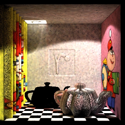
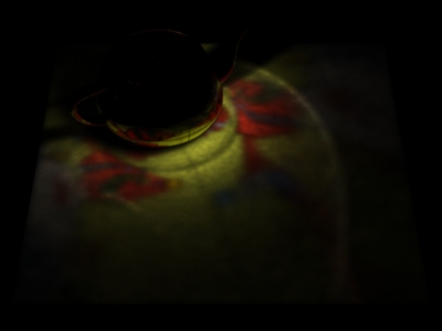
Here is the final image with global illumination. Notice that all illumination on the ceiling (except for the bright "bouncing r" square) is indirect.
Final image with global illumination
If the lines starting with "causticfile" are un-commented, the computed image will also contain caustics caused by specular reflection of light in the chrome teapot.
7 A Caustics Example
The box example shown in the previous sections has caustics from the specular teapot. However, the caustics are not very distinctive. Here is a simpler example with clearer caustics. The scene consists of a textured, specular teapot on a diffuse plane.
Here is the RIB file for baking the direct illumination:
FrameBegin 1

  Format 400 300 1
  ShadingInterpolation "smooth"
  PixelSamples 4 4
  Display "teapotcaustic_bake_direct" "it" "rgba"
  Projection "perspective" "fov" 18
  Translate 0 0.75 5
  Rotate -45 1 0 0

  DisplayChannel "color _irradiance"
  DisplayChannel "vector L"
  DisplayChannel "float _area"

  WorldBegin

    Attribute "cull" "hidden" 0   # ensure illum is baked behind objects
    Attribute "cull" "backfacing" 0   # ensure illum is baked on backsides
    Attribute "dice" "rasterorient" 0   # view-independent dicing

    # Turn on ray-traced shadows
    Attribute "visibility" "transmission" 1
    Attribute "trace" "bias" 0.0001

    # Light source (white spot that bakes its own illumination)
    LightSource "myspotlight" 1
       "point from" [1 1 -1] "vector dir" [-1 -1.5 1] "float coneangle" 0.25
       "string filename" "teapotcaustic_direct.ptc"

    Surface "matte"

    # Teapot (chrome, but matte in this pass)
    AttributeBegin
      Translate -0.35 -1 0.35
      Scale 0.18 0.18 0.18
      Rotate -30 0 1 0
      Rotate -90 1 0 0
      Geometry "teapot"
    AttributeEnd

    # Ground plane
    AttributeBegin
      Polygon "P" [ -1 -1 1  1 -1 1  1 -1 -1  -1 -1 -1 ]
    AttributeEnd

  WorldEnd
FrameEnd
Direct illumination point cloud (channel _irradiance)
Here is the RIB file for baking the scattering coefficients from the textured specular teapot:
FrameBegin 1

  Format 400 300 1
  ShadingInterpolation "smooth"
  PixelSamples 4 4
  Display "teapotcaustic_bake_scattercoeffs" "it" "rgba"
  Projection "perspective" "fov" 18
  Translate 0 0.75 5
  Rotate -45 1 0 0

  DisplayChannel "color diffrefl"   # unused in this example
  DisplayChannel "color specrefl"
  DisplayChannel "color diffrefr"   # unused in this example
  DisplayChannel "color specrefr"   # unused in this example
  DisplayChannel "float ior"        # unused in this example

  WorldBegin

    Attribute "cull" "hidden" 0   # ensure illum is baked behind objects
    Attribute "cull" "backfacing" 0   # ensure illum is baked on backsides
    Attribute "dice" "rasterorient" 0   # view-independent dicing

    # Teapot (textured chrome)
    AttributeBegin
      Surface "bake_scattercoeffs" "color specrefl" [1 1 1]
        "string filename" "teapotcaustic_scattercoeffs.ptc"
        "string displaychannels" "specrefl"
        "string spectexturename" "irma.tex"
        "string texturename" "irma.tex"   # not necessary for caustic
      Translate -0.35 -1 0.35
      Scale 0.18 0.18 0.18
      Rotate -30 0 1 0
      Rotate -90 1 0 0
      Geometry "teapot"
    AttributeEnd

    # Floor
    AttributeBegin
      Surface "constant"
      Polygon "P" [ -1 -1 1  1 -1 1  1 -1 -1  -1 -1 -1 ]
    AttributeEnd

  WorldEnd
FrameEnd
Scattering coefficients point cloud (channel 'specrefl')
In this example, we will use a brick map for the scattering coefficients. The brick map is generated from the point cloud using the brickmake program:
brickmake teapotcaustic_scattercoeffs.ptc teapotcaustic_scattercoeffs.bkm
Next it is time to trace photons. We'll emit 1 million photons with a distribution corresponding to the illumination baked into the teapotcaustic_direct.ptc point cloud file. The photon scattering is controlled by the scattering coefficients stored in the brick map file teapotcaustic_scattercoeffs.bkm. Here is the RIB file for photon emission and scattering:
FrameBegin 1
  Hider "photon" "emissionpointcloud" "teapotcaustic_direct.ptc"
    "emit" 1000000

  Format 400 300 1   # not necessary, but makes ptviewer display nicer
  Projection "perspective" "fov" 18   # ditto

  Translate 0 0.75 5
  Rotate -45 1 0 0

  WorldBegin

    # The name of the caustic photon map file to be written
    Attribute "photon" "causticmap" "teapotcaustic_cpm.ptc"

    # Ray tracing attributes
    Attribute "trace" "maxspeculardepth" 5
    Attribute "trace" "maxdiffusedepth" 5
    Attribute "trace" "bias" 0.0001

    Attribute "dice" "rasterorient" 0 # view-indep dicing to match ptcloud

    # Use surface scattering values in pointcloud or brickmap
    Attribute "photon" "shadingmodel"
      #"pointcloud:teapotcaustic_scattercoeffs.ptc"
      "brickmap:teapotcaustic_scattercoeffs.bkm"

    # Teapot (textured chrome)
    AttributeBegin
      Translate -0.35 -1 0.35
      Scale 0.18 0.18 0.18
      Rotate -30 0 1 0
      Rotate -90 1 0 0
      Geometry "teapot"
    AttributeEnd

    # Matte ground plane
    AttributeBegin
      Attribute "photon" "shadingmodel" "matte"
      Polygon "P" [ -1 -1 1  1 -1 1  1 -1 -1  -1 -1 -1 ]
    AttributeEnd

  WorldEnd
FrameEnd
The result is a caustic photon map file (called teapotcaustic_cpm.ptc) with around 196,000 photons. Displaying the caustic photon map with ptviewer -multiply 2000000 teapotcaustic_cpm.ptc gives the figure below. The colored caustics caused by the texture on the teapot are clearly visible.
Caustic photon map (channel '_power')
The shaders used for rendering the final image are 'paintedchrome' (used for the textured chrome teapot) and 'matte_and_caustic' (used for the ground plane):
surface
paintedchrome (float Kr = 1, Ks = 0, shinyness = 50, samples = 4, blue = 0;
               string texturename = "")
{
  color Crefl, Cspec = 0, tex;
  float depth, s;
  float diffuseraydepth = 0;

  rayinfo("diffusedepth", diffuseraydepth);

  rayinfo("depth", depth);
  s = (depth == 0) ? samples : 1; // only 1 ray for secondary reflections

  if (Kr > 0 && N.I < 0 && diffuseraydepth == 0) {
    normal Nn = normalize(N);
    vector In = normalize(I);
    vector reflDir = reflect(In,Nn);
    Crefl = environment("raytrace", reflDir, "samples", s);
  } else { // don't reflect inside object
    Crefl = 0;
  }

  // Specular highlights
  if (Ks > 0 && diffuseraydepth == 0) {
    vector V = -normalize(I);   // view direction
    normal Nn = normalize(N);
    Cspec = specular(Nn, V, 1/shinyness);
  }

  if (texturename != "") {
    tex = texture(texturename);
    Crefl *= tex;
    Cspec *= tex;
  }

  Ci = Kr * Crefl + Ks * Cspec + color(0, 0, blue);
  Oi = 1;
}
surface
matte_and_caustic(uniform string filename = "";
                  float Ka = 1, Kd = 1, Kc = 1, nphotons = 50)
{
  color irrad = 0;
  normal Nn = normalize(N);

  irrad = Ka * ambient() + Kd * diffuse(Nn);
  irrad += Kc * photonmap(filename, P, Nn, "estimator", nphotons);

  Ci = Kd * Cs * irrad;
  Ci *= Os; // premultiply opacity
  Oi = Os;
}
Here is the RIB file for rendering the computed caustics:
FrameBegin 1

  Format 400 300 1
  ShadingInterpolation "smooth"
  PixelSamples 4 4
  Display "teapotcaustic_render" "it" "rgba"
  Projection "perspective" "fov" 18
  Translate 0 0.75 5
  Rotate -45 1 0 0

  WorldBegin

    # Turn on ray-traced reflections and shadows
    Attribute "visibility" "specular" 1
    Attribute "visibility" "transmission" 1
    Attribute "trace" "bias" 0.0001

    # Light source
    LightSource "myspotlight" 1   # white spot
       "point from" [1 1 -1] "vector dir" [-1 -1.5 1] "float coneangle" 0.25
    LightSource "ambientlight" 2 "float intensity" 0.1

    # Teapot (textured chrome)
    AttributeBegin
      Surface "paintedchrome" "float Kr" 1 "float Ks" 1 "float shinyness" 25
        "string texturename" "irma.tex"
      Translate -0.35 -1 0.35
      Scale 0.18 0.18 0.18
      Rotate -30 0 1 0
      Rotate -90 1 0 0
      Geometry "teapot"
    AttributeEnd

    # Ground plane
    AttributeBegin
      Surface "matte_and_caustic" "filename" "teapotcaustic_cpm.ptc"
       "float nphotons" 200 "float Kc" 6
      Polygon "P" [ -1 -1 1  1 -1 1  1 -1 -1  -1 -1 -1 ]
    AttributeEnd

  WorldEnd
FrameEnd
Since the caustic is spread out it is rather dim (unlike a focused caustic). For that reason we used a "Kc" value of 6 to brighten it artificially. Here is the caustic by itself and with direct illumination:
Caustic |
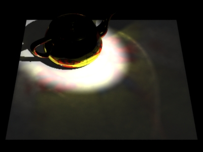
Caustic plus direct illumination |
In this example neither the caustic casting object nor the caustic receivers are displacement mapped, but they could easily have been.
8 Known Limitations
The implementation has the following known limitations:
- PRMan can currently only handle one point cloud (or one brick map) for scattering coefficients. It would be nice to have the possibility of having more point clouds and brick maps, for example one per object.
- No glossy reflection or refraction (neither isotropic nor anisotropic) in the photon scattering phase.
- When baked scattering coefficients are used, we can't do direction-dependent scattering coefficients such as the Fresnel formulas. (Use the built-in material "glass" for glass with Fresnel reflection and refraction.)
9 Appendix A
9.1 Displacement shaders
The shader 'dispmap' uses a texture map for displacement, 'dispsinz' computes a wavy displacement depending on the z position (depth), and 'disppumpkin' computes a displacement that makes a teapot look like a pumpkin.
displacement
dispmap (string texturename = ""; float scale = 1.0, invert = 0)
{
  color tex;
  vector Nn = normalize(N);
  float avetex, disp;

  // Compute displacement
  tex = texture(texturename);
  avetex = (tex[0] + tex[1] + tex[2]) / 3;
  if (invert != 0) // convert bright to dark and vice versa
    avetex = 1 - avetex;
  disp = scale * avetex;

  // Displace P and calculate the new normal
  P = P + disp * Nn;
  N = calculatenormal(P);
}
displacement
dispsinz (float freq = 1.0, scale = 1.0)
{
  // Calculate displacement
  point Pobject = transform("object", P);
  float z = zcomp(Pobject);
  float disp = scale * sin(freq*z);

  // Displace position and calculate the new normal
  P = P + disp * normalize(N);
  N = calculatenormal(P);
}
displacement
disppumpkin (float freq = 1, scale = 0.1)
{
  // Convert N from current (camera) space to object space
  vector Nobj = normalize(vtransform("object", N));

  // Compute displacement
  float angle = atan(ycomp(Nobj), xcomp(Nobj));
  float disp = scale * cos(freq*angle);

  // Displace position and calculate the new normal
  P = P + disp * normalize(N);
  N = calculatenormal(P);
}