Per-Face Textures
Per-Face Textures
September, 2009
Introduction
As of version 15, RenderMan Pro Server supports per-face texture mapping, also known as Ptex. Ptex is a texture mapping system that uses the intrinsic per-face UVs of a polygonal mesh; no explicit texture parameterization is required. Ptex textures are stored along with adjacency data in a single file per primitive. Ptex uses the adjacency data to perform seamless anisotropic filtering of multi-resolution textures across surfaces of arbitrary topology. Additional technical information about Ptex textures and filtering can be found at http://www.disneyanimation.com/library/ptex
To help kick start the process of authoring Ptex files, this appnote provides details of shaders and utility programs that can be used to bake shaded results into Ptex textures. A parameter, __faceindex, which labels each face on the geometry, is required by the ptexture() shading function and we provide a RIF called RifSubdivFaceIndex that will label geometry with the appropiate index. We also provide a program called ptxmake that will take a pointcloud baked in a specific way and convert the data to a Ptex file.
Geometric Primitive Support
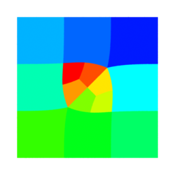
One of the required parameters for the ptexture() call is __faceindex. This index is a facevarying, postive integer at each quad face of the surface, usually starting at 0. For Catmull-Clark surfaces, non-quad faces are numbered at each vertex, and the first level of subdivision of the non-quad faces will generate N-subfaces, where N is the number of vertices. For quad faces, the same faceindex` value is used on each vertex. An example of the faceindex layout is shown below. Note that the __faceindex follows special subdivision rules that will ensure the value is constant across quad-faces and that the shader parameter will be of varying detail. For Loop surfaces, only triangular faces are supported; each vertex of the face should be numbered with the same __faceindex value.
|
|
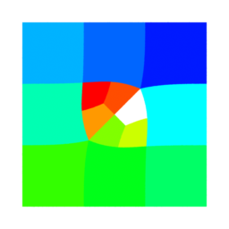
| showfaceindex applied to surface | showfaceindex indicating faceindex 3 |
Here is the RIB file that generated the images above:
##RenderMan RIB
version 3.04
Projection "perspective" "fov" [45]
FrameBegin 0
Display "faceindex" "framebuffer" "rgba"
Format 256 256 1.0
PixelSamples 4 4
WorldBegin
Translate 0 0 3
AttributeBegin
Surface "showfaceindex"
SubdivisionMesh "catmull-clark"
[4 4 4 4 3 3 4 4 4 4]
[4 5 1 0 5 6 2 1 6 7 3 2
 8 9 5 4 9 10 5 10  6 5
 10 11 7 6 12 13 9 8
 13 14 10 9 14 15 11 10]
["interpolateboundary" "smoothtriangles"] [0 0 1 0] [1] []
"P" [-1.0 -1.0 0
    -0.3333333333333 -1.0 0
    0.3333333333333 -1.0 0
    1.0 -1.0 0

    -1.0 -0.3333333333333 0
    -0.3333333333333 -0.3333333333333 0
     0.3333333333333 -0.3333333333333 0
     1.0 -0.3333333333333 0

     -1.0 0.3333333333333 0
     -0.3333333333333 0.3333333333333 0
      0.3333333333333 0.3333333333333 0
     1.0 0.3333333333333 0

     -1.0 1.0 0
     -0.3333333333333 1.0 0
     0.3333333333333 1.0 0
     1.0 1.0 0]
"facevarying float __faceindex"
[6 6 6 6
 7 7 7 7
 8 8 8 8
 9 9 9 9

 0 1 2
 3 4 5
 10 10 10 10
 11 11 11 11

 12 12 12 12
 13 13 13 13]
"constant string __handleid" ["plate"]

AttributeEnd
WorldEnd
FrameEnd
And here is the corresponding shader:
surface showfaceindex(varying float __faceindex = -1; float whiteface = -1)
{
   if (__faceindex == whiteface) {
        Ci = color(1, 1, 1);
   } else {
        Ci = color "hsl" (__faceindex / 20.0, 1.0, 0.5);
   }
   Oi = Os;
}
A RIF called RifSubdivFaceIndex.so is included for convenience that will take a subdivision surface without a faceindex and create the appropriate __faceindex values at each vertex.
ptxmake
A new utility program called ptxmake has been created that will take data baked into a point cloud and convert it into a Ptex texture file. The usage is as follows:
ptxmake [options] ptcfile channelname ptxfile
ptxmake supports the following options:
| -fedfile (fedfilename) | provide a face edge data file |
| -geometry (quad|tri) | provide the geometry of the baked data quad |
| -depth (byte|short|half|float) | bit depth of output image, the default is half |
| -splat (none|diffusion|smooth|area) | splattering mode, the default is diffusion |
| -newer (0|1) | convert if (and only if) the ptcfile is newer than the ptxfile |
| -verbose | enables verbose output |
| -outofcore | work out of core for large data |
| -v|-version | output version string |
Baking for ptxmake
In the example below we are baking occlusion onto the dragon model and then converting the occlusion data to a Ptex formatted file (.ptx). The Ptex file will be significantly smaller than the pointcloud and will re-render faster, using less memory than an organized pointcloud.
Point cloud data need to be formatted a specific way for ptxmake. The shader below shows that we have placed the u,v and __faceindex into P and used that as the point to bake. Notice that we have turned interpolation on, to prevent artifacts at grid boundaries. Additionally, to prevent imprecision in camera transformations and invalid transformations on the faceindex component of the point data, we have disabled coordinate system transforms.
surface bakePtxOcc(string filename="", displaychannels=""; float samples=512, maxvariation=0.02;
                   varying float __faceindex=0)
{

  // Compute occlusion
  float occ = occlusion(P, N, samples, "maxvariation", maxvariation);

  // Set Ci and Oi
  Ci = (1 - occ) * Cs * Os;
  Oi = Os;

  // Construct Point data for Ptex.
  point facedata;
  facedata[0] = u;
  facedata[1] = v;
  facedata[2] = __faceindex;

  normal ImageN = normal(0,0,1);
  bake3d(filename, displaychannels, facedata, ImageN,
         "coordsystem", "_disable", "interpolate", 1,
         "occlusion", (1.0-occ));
}
In the RIB file below notice there are a few settings we have used to obtain ideal baking for the Ptex file. First off it is best to use an orthographic projection with raster-oriented dicing turned off. This helps dice the grids more uniformly. We have also turned on binary dicing and turned off stitching (stitching disables binary dicing). If memory allows, it is also nice to increase the grid size and bucket size. Finally, as is common with most baking, we have disabled culling.
##RenderMan RIB-Structure 1.1
version 3.04
Display "dragonBake.tif" "framebuffer" "rgba"
DisplayChannel "float occlusion"
Format 1024 1024 1
PixelSamples 2 2

# Best for baking Ptex
Option "limits" "bucketsize" [128 128]
Option "limits" "gridsize" [15000]
Attribute "dice" "binary" [1]
Attribute "dice" "int stitch" [0]
Attribute "cull" "int backfacing" [0]
Attribute "cull" "int hidden" [0]
Attribute "dice" "int rasterorient" [0]

Sides 2
Projection "orthographic"
ScreenWindow -4 4 -7 8
Clipping 0.01 1000
ShadingRate 1

WorldBegin
Attribute "visibility" "trace" [1]
Translate 0 0 10
Surface "bakePtxOcc" "float samples" [128] "string filename" ["dragon.ptc"]
       "string displaychannels" ["occlusion"]
ReadArchive "./dragon.rib"
WorldEnd
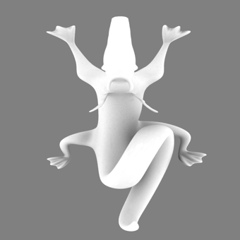
occlusion baked onto dragon
One of the key components of a Ptex file is the face and edge connectivity data of the geometry being textured. A RIF, called RifFaceEdgeData, has been provided that takes a surface that has been tagged with __handleid and generates a file called: __handleid.fed. This fed file can then be passed to the ptxmake program. Note, a limitation of the RifFaceEdgeData plugin is that it can only be used while rendering with prman. It will not function with catrib or prman with the -catrib option. In addition to the connectivity data, the fedfile also encodes the geometry type, so the -geom flag does not need to be used with ptxmake, except in cases where no fedfile is present.
Using ptxmake
After baking, the ptxmake program is used to convert the point cloud data into a Ptex file. The usage for our dragon test case is:
ptxmake -depth half -fedfile dragon.fed dragon.ptc occlusion dragon.ptx
This takes the .fed file and the .ptc file generated during the bake pass and renders each face in the point cloud into a per-face texture in the .ptx file. This file can then be used to re-render the baked occlusion data. Notice, Ptex files support the half-float data format.
The utility program ptxinfo can be used to query data about the ptx file. In our test case ptxinfo -f dragon.ptx gives the following output:
meshType: quad
dataType: float16
numChannels: 1
alphaChannel: (none)
numFaces: 895
  hasFaceEdits: no
numMetaKeys: 0
face 0:  res: 7 7 (128 x 128)  adjface: 85 1 6 5  adjedge: 3 3 0 1  flags: (none)
face 1:  res: 7 7 (128 x 128)  adjface: 88 2 7 0  adjedge: 3 3 0 1  flags: (none)
face 2:  res: 7 7 (128 x 128)  adjface: 91 3 8 1  adjedge: 3 3 0 1  flags: (none)
face 3:  res: 7 7 (128 x 128)  adjface: 94 4 9 2  adjedge: 3 3 0 1  flags: constant
face 4:  res: 7 7 (128 x 128)  adjface: 97 5 10 3  adjedge: 3 3 0 1  flags: constant
face 5:  res: 7 7 (128 x 128)  adjface: 100 0 11 4  adjedge: 3 3 0 1  flags: (none)
face 6:  res: 7 7 (128 x 128)  adjface: 0 7 12 11  adjedge: 2 3 0 1  flags: (none)
...
The shader that utilizes the Ptex file is show below. Note that the ptexture() call is very similar to the texture() call. There are a few key differences. The channel selector is an explicit argument to ptexture(), and __faceindex is a required parameter.
surface ptxOcclusion(string mapname=""; varying float __faceindex=0)
{
   // Get back the occlusion results from a ptexture file
   float occ = ptexture(mapname, 0, __faceindex);

   // Set Ci and Oi
   Ci = occ * Cs * Os;
   Oi = Os;
}
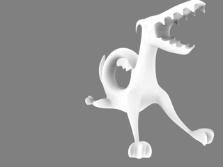
In the examples above, the .ptc file is around 120 megabytes and the resulting .ptx file ends up at 12 megabytes. A comparison of the results from the occlusion() call and the ptexture() call are below.

|
|
| dragon rendered with ptexture() | dragon rendered with occlusion() |
Ptexture and filtering
The ptexture() call requires a filter-region for specifying a region to filter over. By default, the call generates an appropriate filter-region for either the Catmull Clark surface or the Loop surface. The sharpest, ideal filter-region for a Catmull Clark surface can also be create manually as shown in the code below.
surface ptxQuadOcclusion(string mapname=""; varying float __faceindex=0)
{
   // Create ideal filterregion for ptexture on a Catmull Clark surface
   filterregion fr;
   fr->calculate2d(u,v,du,0,0,dv);

   // Get back the occlusion results from a ptexture file
   float occ = ptexture(mapname, 0, __faceindex, fr);

   // Set Ci and Oi
   Ci = occ * Cs * Os;
   Oi = Os;
}
For a Loop surface, the ideal filter-region is constructed differently. It should not specify the axis of the region, as exemplified in the example code below:
surface ptxLoopOcclusion(string mapname=""; varying float __faceindex=0)
{
   // Create ideal filterregion for ptexture on a Loop surface
   filterregion fr;
   fr->calculate2d(u,v);

   // Get back the occlusion results from a ptexture file
   float occ = ptexture(mapname, 0, __faceindex, fr);

   // Set Ci and Oi
   Ci = occ * Cs * Os;
   Oi = Os;
}
Per-Face Environment Cubes
txmake
Ptex files make ideal candidates for environment cubes. Because of the cross-face filtering capabilities in Ptex, blurs on cubemaps filter well.
txmake now takes a -penvcube argument and creates a Ptex envcube. This cubemap can be used by the environment() function, just like any other environment cube texture. Below are the results of a half-format HDR environement cube that has been blurred.
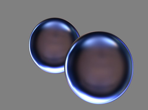
spheres reflecting blurry Ptex envcubes